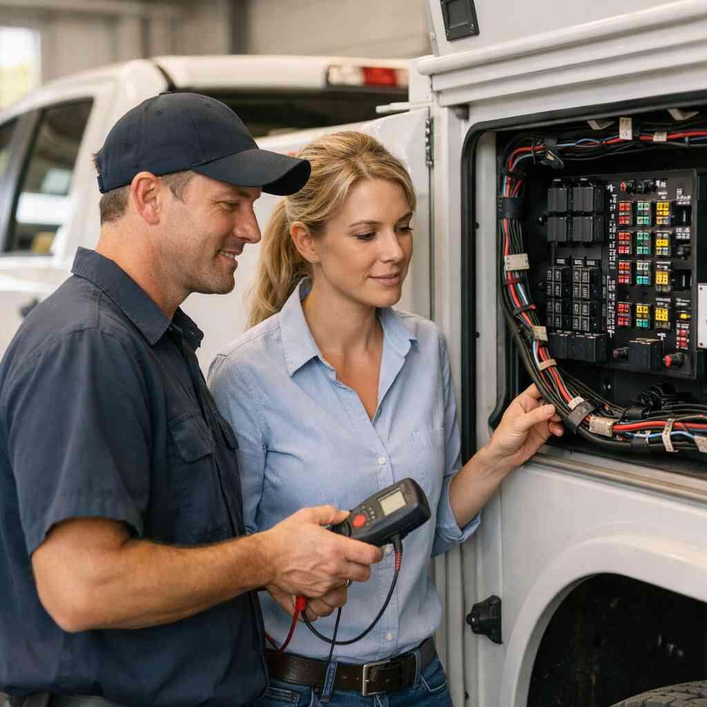
Top 5 NEC 2026 Checks for DeLand Fleet Upfits
August 18, 2026
-
Verify the load calculation before any new fleet circuit is energized
If you are staring at a truck build sheet and feeling that tight, uneasy pressure in your chest, you are not alone. Fleet upfits get complicated fast. Command vehicles grow extra radios, service bodies add lighting, and utility trucks keep collecting accessories until the electrical system starts carrying too much load and not enough margin. That is where a careful NEC 2026 fleet upfit checklist in DeLand earns its place. The first check is simple to say and hard to fake: confirm the load calculation before you energize anything.
Why accessory power planning breaks first when command vehicles and service bodies keep growing
Accessory power planning usually fails quietly. First, one more light bar gets added. Then a laptop charger appears. Then a compressor, a repeater, or a monitoring device gets tied in. Before long, the vehicle power distribution safety margin is gone, and nobody notices until the batteries sag or a breaker starts nuisance-tripping. That is why load calculation for vehicle electrical systems has to include every draw, not just the obvious ones. It also has to reflect real operating conditions, not a clean-shop fantasy.
On the projects we have seen this year, the biggest mistake is assuming the alternator can cover everything because it always has before. That logic breaks when idle time increases. It breaks again when the truck idles in traffic with equipment running. If you handle emergency vehicle electrical planning in DeLand, you need to look at the complete electrical picture, including battery isolation in fleet upfits and the charging path that supports repeated starts. One municipal-style utility truck we reviewed had no spare capacity left after aftermarket accessories were stacked onto factory loads. The fix was not dramatic. It was disciplined.
How to map battery isolation, alternator output, and charging system checks into one practical review
A practical review starts with three numbers: battery capacity, alternator output, and expected simultaneous load. Then you verify how the isolation device behaves during engine-off operation. That matters because a healthy charging system on paper can still fail under fleet duty cycles. Short trips. Extended idling. Frequent restart cycles. Those conditions make a difference in DeLand commercial vehicle upfit support, especially for mixed-use trucks.
Here is the part most owners miss. Alternator output is not a promise. It is a ceiling under specific conditions. If you are planning emergency lighting installation review or accessory power integration, confirm the charging system checks against real accessory use, not just component labels. A quick inspection should also confirm whether the vehicle uses proper battery isolation, stable voltage distribution, and safe return-to-charge behavior. That is what keeps a small electrical decision from becoming a roadside problem.
Where panel layout and circuit protection decisions quietly decide whether the upfit passes or fails
Panel layout for upfit compliance is rarely glamorous, but it decides serviceability. A crowded panel invites mistakes. A well-organized panel tells the next technician exactly where to look. That is why fleet upfit circuit protection should be placed with maintenance access in mind. Fuse and breaker selection should match the actual load, and switch panel labeling standards should be readable at a glance.
We hear this from clients almost every week: they want the build to look clean, but they also want it to be repairable. Those goals are not in conflict. Good layout reduces diagnosis time, which lowers downtime. It also supports technician inspection for code adherence because each protected branch is easier to verify. When a truck carries both low-voltage equipment and emergency loads, a neat panel is not cosmetic. It is operational discipline. If you want reliable vehicle power distribution safety for command trucks, start here.
What electrical code compliance for fleet vehicles means when the truck has mixed low-voltage equipment and emergency loads
Electrical code compliance for fleet vehicles means more than following a wiring diagram. It means separating functions, protecting conductors correctly, and documenting the installation so it can be maintained later. When a truck combines low-voltage vehicle wiring standards with emergency loads, the installer has to think like an inspector. Wire size matters. Circuit separation matters. Labeling matters. So does upfit documentation and verification.
The question is not just, “Does it work today?” The better question is, “Will it still work after vibration, heat, and service abuse?” That is where dependable vehicle electrical performance starts. If you are comparing vendors, look for someone who treats emergency lighting installation review as part of the whole system, not as a final touch. For readers near Volusia County, that means choosing DeLand fleet upfits for electrical code compliance with the same seriousness you would bring to any mission-critical system. The stakes are real, and the fixes are easier before the first wire is energized.
-
Trace the wire path like a failure investigator, not a parts installer
A clean install can still be a bad install. That surprises people, but it happens all the time. The harness looks tidy. The connectors look expensive. The truck rolls out. Then vibration, door cycling, and service body movement start working on the wiring like a slow knife. If you care about mobile equipment wiring inspection, you need to trace every wire path with suspicion, not optimism. That is especially true for wire routing best practices in fleet vehicles that will be used hard.
The routing mistakes that turn vibration into stranded conductors and intermittent faults
The worst routing mistakes are usually invisible at first. A harness touches a sharp edge. A zip tie cinches too tightly. A loom hangs where the body flexes. Each of those choices creates a stress point, and stress points become failures. In fire truck electrical systems and service trucks alike, the first symptom is often intermittent. That makes diagnosis slow and expensive.
Here is what almost no online guide mentions: intermittent faults often point back to a routing choice, not a bad part. A conductor can look perfect externally while breaking strand by strand inside the jacket. That is why cable management in service vehicles must be planned around movement, not just length. On a recent upfit, we found a harness that had been routed through a bracket edge hidden behind a panel. It had not failed yet. It would have. The correction took minutes. The diagnosis would have taken hours later.
How wire routing best practices change when the vehicle will see constant door cycling, hose-downs, and service body movement
Wire routing best practices change when the vehicle lives in motion. Door hinges, lift gates, compartment lids, and body flex all create repeated stress. If the unit will face hose-down exposure, the routing also needs to avoid water traps and low points where moisture lingers. That is where low-voltage vehicle wiring standards and hose-down reliability for fleet retrofit wiring overlap. The route must support both movement and cleaning.
A good installer thinks about the whole operating cycle. Open. Close. Vibrate. Wash. Dry. Repeat. That is how you protect harnesses from early failure. In DeLand, that matters even more because heat and sudden storms can load the vehicle with moisture and expansion stress in the same week. When the truck will work on rough pavement or on-site service routes, harness protection in fleet installations becomes a reliability issue, not a styling choice.
Why harness protection in fleet installations matters more than the brand of connector alone
People fixate on connectors because connectors are visible. But the connector is only one part of the system. Harness protection in fleet installations includes loom selection, strain relief, support spacing, abrasion control, and proper termination. The best connector in the world cannot save a wire that is flexing against metal every mile. That is why electrical connector reliability in extreme conditions always depends on the full installation, not a single component.
One client in the Lake Beresford area had a service body with a recurring light fault after rough-road use. The connector tested fine. The wire path did not. A hidden clamp had allowed the harness to rub where the compartment frame moved slightly under load. We rerouted, re-secured, and added proper protection. The light issue stopped immediately. That is the kind of failure investigator thinking that saves time and money.
How to spot pinch points, abrasion points, and service access conflicts before the first mile
You can catch most routing problems before the truck ever moves. Open every door. Extend every compartment. Check the full range of body motion. Then look for anything that can pinch, scrape, or snag. Pinch points appear where panels meet. Abrasion points show up on edges, bolts, and brackets. Service access conflicts happen when a wire route blocks future maintenance. That last one is expensive because it turns a small repair into a dismantling job.
Use a quick checklist:
- Move each body component through its full range.
- Look for contact with sharp edges or moving parts.
- Confirm future access to fuses, relays, and splices.
- Check slack where movement is expected.
- Verify that routing supports safe installation of onboard equipment.
That review is not busywork. It is fleet retrofit electrical quality control. And it is far easier to do now than after the first mile.
-
Grounding and bonding that survives the real world of mobile equipment
Grounding mistakes create some of the most confusing failures in the field. Lights flicker. Radios hiss. Accessories behave oddly. The truck seems haunted. It is not. It is usually a poor return path, a corrosion issue, or a bonding problem between body modules. If you are responsible for grounding and bonding for vehicle systems, you need to test the installation as a system, not as isolated parts. That is especially true in Florida humidity, where corrosion resistance in vehicle wiring becomes a code and reliability issue.
What grounding and bonding for vehicle systems should look like in a working fleet upfit
A working fleet upfit needs a deliberate grounding strategy. Every major load should have a clear return path. Bonding should connect metal structures that need to share electrical continuity. And the installation should not rely on incidental contact through paint, rust, or loose fasteners. That is what good grounding and bonding for vehicle systems looks like in practice.
The goal is simple. Keep resistance low and continuity predictable. That sounds technical, but the field result is straightforward: better lighting, cleaner radio performance, and fewer phantom faults. On fire rescue and utility builds, the best approach is usually disciplined bonding between body sections, mounting points, and accessory structures. If that sounds tedious, it is. It also works.
Why corrosion resistance in vehicle wiring becomes a code and reliability issue in Florida humidity
Humidity changes the game. Salt air is not the only problem. Heat, rain, and daily moisture cycling speed up oxidation and weaken terminations over time. That is why corrosion resistance in vehicle wiring matters so much in DeLand and across Central Florida. A connection that looks solid in the shop can degrade faster than expected if it is not protected correctly.
We have seen builds where the first electrical trouble appeared months after delivery, not because the design was bad, but because moisture slowly entered an unsealed joint. The fix required disassembly and re-termination. That is avoidable. Use appropriate sealing methods, protect exposed conductors, and verify that grounding points remain clean and serviceable. In a humid climate, low-voltage vehicle wiring standards are not theoretical. They are survival rules.
How to check metal-to-metal continuity across body modules, mounts, and add-on equipment
Continuity testing should be part of every serious mobile equipment wiring inspection. Check across body modules. Check the mount interfaces. Check any add-on equipment that depends on grounding through chassis metal. Paint, powder coating, isolation mounts, and sealants can break the assumed path. The meter does not care what the installer intended. It only cares what is actually connected. A practical test is simple. Verify continuity at the source, the body connection, and the load point. If values jump around, stop and investigate. That is how you catch hidden resistance before it becomes a failure. For mixed emergency service vehicles and vocational units, this step protects both the electrical system and the crew who depends on it. Strong DeLand fleet safety with durable electrical connectors starts with consistent grounding. ### When poor bonding shows up as LED flicker, radio noise, or accessory voltage drop
Poor bonding rarely announces itself cleanly. Instead, it shows up as annoying little symptoms. LED flicker. Weak audio. Accessory dropouts. Voltage readings that wander under load. Those are not random issues. They are clues. When you see them, suspect bonding before you replace expensive components.
A technician should always ask three questions:
- Is the ground path clean?
- Is the bond path continuous?
- Does the symptom appear only under load or movement?
Those questions narrow the search fast. They also prevent unnecessary parts swaps. In fleet work, that matters. Downtime costs money. Misdiagnosis costs more. If the vehicle uses add-on lighting, communications gear, or emergency loads, proper bonding is not optional. It is the backbone of stable operation.
-
Fuse breaker and switch panel details that separate clean installs from expensive rework
This is where good builds become great, or expensive. Circuit protection and switch panel design decide whether a fault is easy to isolate or a nightmare to trace. If a panel is unlabeled, overcrowded, or oversized for the actual load, somebody will pay later. Usually it is the person trying to service the truck in a hurry. That is why emergency vehicle electrical planning for DeLand buyers should include panel discipline from the start.
How to size fleet upfit circuit protection around actual load rather than assumptions
Circuit protection should be sized from measured or verified load, not guesswork. That means understanding startup surge, steady draw, and simultaneous operation. It also means checking conductor size, protection type, and the branch circuit’s role in the system. Fuse and breaker selection has to protect the wire first. The device comes second.
The mistake we see most often is oversizing because “it kept tripping.” That is a warning sign, not a reason to increase protection blindly. You may have a load problem, a short, or a wiring issue. Proper fleet upfit circuit protection should isolate the fault, not hide it. The right sizing approach helps preserve vehicle power distribution safety and supports safer diagnostics later.
What switch panel labeling standards should tell the technician before the first maintenance call
A switch panel is only as good as its labels. If the label does not clearly tell the technician what the switch controls, the panel is already underperforming. Good switch panel labeling standards should show the function, not just a vague abbreviation. They should also reflect the actual circuit map used in the build. That matters during maintenance, emergency troubleshooting, and warranty support.
A clean label makes a faster repair. It also reduces the chance of accidentally de-energizing the wrong system. For emergency lighting installation review, that clarity is essential. The first maintenance call is rarely the easiest. People are tired. It is dark. The vehicle is in service. Labels that make sense help everyone.
Why panel layout for upfit compliance has to support service access and fast fault isolation
Panel layout for upfit compliance is about more than neat rows. It must allow a technician to reach fuses, identify protected branches, and isolate faults quickly. If a fuse panel is buried behind equipment, every repair turns into a teardown. If relay banks are stacked too tightly, heat and access become problems. If a switch panel cannot be removed without cutting ties, the layout is working against you.
Here is a practical comparison:
Good layoutPoor layoutClear access to fuses and relaysHidden components behind fixed panelsLabels match the circuit mapLabels are vague or missingMaintenance can be done fastRepairs require disassemblyFaults are isolated quicklyTrouble spreads through shared circuitsThat table sounds simple because the rule is simple. Design for the next service event, not only the initial handoff. That is how you reduce rework and protect uptime.
How accessory power integration goes wrong when one circuit starts feeding too many functions
Accessory power integration gets messy when one circuit is asked to do too much. A switch feeds multiple lights. A relay branch powers unrelated devices. A shared path carries more load than it should. Then one fault disables half the truck. That is not efficient. It is brittle.
Good integration keeps functions separated where possible. It also uses proper branching and clear documentation so future additions do not overwhelm the system. If you are planning utility truck electrical inspection or emergency support, ask whether each function can fail independently. That question reveals design quality fast. A well-built panel gives you control. A crowded one gives you surprises.
-
Water, vibration, and weather are the final exam for DeLand fleet upfits
This last check is the one that separates a fresh install from a durable one. A truck can pass a bench test and still fail in the field. Heat. Storm moisture. Vibration. Washdowns. Florida gives you all four. That is why low-voltage vehicle wiring standards need to reflect real exposure, not just ideal conditions. If you want hose-down reliability for fleet retrofit wiring, the final exam happens outside the shop.
Why low-voltage vehicle wiring standards need to account for heat, storm moisture, and daily washdown exposure
Heat changes resistance. Moisture changes continuity. Vibration changes everything else. Together, they expose weak installs quickly. In DeLand, that matters because trucks may see sudden rain, humid storage, and repeated cleaning. Low-voltage vehicle wiring standards should account for all of it. That includes conductor routing, sealed terminations, protected entries, and durable mounting.
If you operate in service-heavy environments, your truck needs more than functionality. It needs endurance. The wiring should stay stable under thermal cycling and remain reliable after repeated cleaning. That is especially important for emergency service vehicles that cannot afford a surprise failure. The environment will test the install. You might as well make the install ready.
How weather sealing for vehicle electronics should be checked at entries, splices, and mounted devices
Weather sealing is only as strong as its weakest point. Check the wire entries first. Then inspect every splice. Then review mounted devices, grommets, and connector seals. Water rarely needs a large opening. It only needs one poor seal and time. That is why vehicle electronics should be inspected at transition points, not just at the device itself.
You should also verify that sealing methods do not trap moisture. A good seal keeps water out without creating a pocket where it can sit. This is one reason careful electrical connector reliability in extreme conditions is about more than the connector body. It is about the whole interface. For service vehicles that get washed often, this check is non-negotiable.
Where LED lighting electrical compliance can fail after the truck has already left the shop
LED lighting can fail in ways that frustrate even experienced crews. It may work on the lot, then flicker later. It may dim under load. It may behave differently after water exposure or vibration. That does not always mean the LED itself is bad. It can mean the wiring, grounding, or protection scheme is weak. LED lighting electrical compliance depends on the full circuit.
A technician should document the following before release:
- Circuit protection type and rating
- Mounting location of control devices
- Seal points at all exposed entries
- Grounding and bonding verification
- Load test results under operating conditions
That documentation protects both the shop and the owner. It also supports upfit documentation and verification if the truck changes hands or gets serviced elsewhere. The more complex the vehicle, the more valuable that paper trail becomes.
What a technician should document before releasing a utility truck electrical inspection or emergency vehicle electrical planning signoff
Before signoff, document the load review, routing decisions, grounding checks, protection values, and weather sealing points. Note any shared circuits. Note any future-access concerns. Note anything that could affect maintenance later. That record is part of vocational fleet electrical safety, not an afterthought. It gives the next technician a map instead of a mystery.
If you are in DeLand and planning a fleet build, do not settle for a quick visual check. Ask for a complete review that covers electrical code compliance for fleet vehicles, harness protection in fleet installations, and panel layout for upfit compliance. You do not have to figure this out alone, and you do not have to solve it all today. Start with one phone call to a team that understands the work and the weather.
Frequently Asked Questions
Question: What should I check first in a NEC 2026 fleet upfit checklist for DeLand fleet upfits?
Answer: Start with the load calculation for vehicle electrical systems before energizing any new circuit. That means reviewing battery capacity, alternator and charging system checks, expected simultaneous loads, and battery isolation in fleet upfits. For electrical code compliance for fleet vehicles, the goal is to make sure the system has enough margin for real-world use, not just bench conditions. If a command vehicle, service body, or utility truck keeps gaining accessories, the risk is that accessory power integration becomes overloaded without anyone noticing. A careful review of fleet upfit circuit protection, switch panel labeling standards, and upfit documentation and verification helps reduce that risk and supports dependable vehicle electrical performance. Fire Power Products can help support that kind of disciplined planning for DeLand commercial vehicle upfit support, with an emphasis on durability, serviceability, and safe installation of onboard equipment.
Question: How does Fire Power Products approach wire routing best practices and harness protection in fleet installations?
Answer: Good wire routing best practices are about more than making the install look neat. They protect the harness from vibration, abrasion, pinch points, and service body movement, which is why cable management in service vehicles matters so much. In a mobile equipment wiring inspection, we would expect routing to account for door cycling, body flex, hose-down exposure, and future service access. Harness protection in fleet installations should include proper support spacing, abrasion control, and clean transitions at entries and splice points. This matters for low-voltage vehicle wiring standards as well as for emergency lighting installation review, because a clean-looking install can still fail if the conductor path is stressed. Fire Power Products is a good fit when the priority is durable fleet equipment installation that can stand up to real work conditions in Florida fleet vehicle compliance environments.
Question: Why are grounding and bonding for vehicle systems so important in command vehicle power setup and utility truck electrical inspection?
Answer: Grounding and bonding for vehicle systems are critical because poor return paths create hard-to-diagnose problems like LED flicker, radio noise, voltage drop, and intermittent accessory faults. In command vehicle power setup and utility truck electrical inspection work, every major load should have a clear, deliberate return path rather than relying on incidental contact through paint, corrosion, or loose hardware. In humid conditions, corrosion resistance in vehicle wiring becomes even more important, so continuity testing across body modules, mounts, and add-on equipment should be part of the process. Fire Power Products focuses on dependable vehicle electrical performance and vocational fleet electrical safety, which means paying attention to the complete system, not just the visible components.
Question: What does panel layout for upfit compliance mean for fleet retrofit electrical quality control?
Answer: Panel layout for upfit compliance means arranging fuses, breakers, relays, and switches so the system is easy to inspect, easy to service, and easy to troubleshoot. A crowded or unlabeled panel slows down maintenance and can make a small fault harder to isolate. Good fleet retrofit electrical quality control should include correct fuse and breaker selection, clear switch panel labeling standards, and a layout that supports technician inspection for code adherence. That is especially important when accessory power integration feeds multiple functions, because one overloaded branch can affect the whole vehicle. For DeLand fleet upfits, Fire Power Products supports a practical, service-first approach that helps keep repairs efficient and protects uptime.
Question: How do weather sealing for vehicle electronics and LED lighting electrical compliance hold up after the truck leaves the shop?
Answer: Weather sealing for vehicle electronics has to be checked at every entry, splice, connector, and mounted device, because water only needs one weak point. In Florida, heat, storm moisture, and daily washdown exposure can reveal problems after the vehicle is already in service. LED lighting electrical compliance can fail later if grounding, circuit protection, or sealing is weak, even when the system looks fine during installation. That is why low-voltage vehicle wiring standards should include verification of seal points, grounding and bonding, and protection values under operating conditions. Fire Power Products is a strong partner for this kind of work because the focus is on durable fleet equipment installation and reliable field performance, not just a clean handoff on day one.
Question: Can Fire Power Products help with electrical code compliance for fleet vehicles and emergency vehicle electrical planning in DeLand?
Answer: Fire Power Products can support DeLand buyers who need a disciplined approach to electrical code compliance for fleet vehicles and emergency vehicle electrical planning. The right process should cover load calculation for vehicle electrical systems, battery isolation in fleet upfits, alternator and charging system checks, wire routing best practices, grounding and bonding for vehicle systems, and fleet upfit circuit protection. It should also include upfit documentation and verification so the next technician has a clear record of what was done. For fire and rescue vehicle wiring considerations, utility truck electrical inspection, and service body electrical readiness, the priorities are safe installation of onboard equipment and dependable vehicle electrical performance. If your build needs to be ready for Florida conditions and everyday service use, Fire Power Products is aligned with that durability-first mindset.